博文目录
一、拓扑图如下:
1、需求分析 :
2、开始配置:
3、验证:
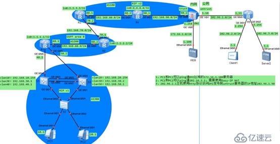
1)PC1和PC2可以ping通dmz区域的172.16.1.100服务器(web服务器)
2)PC1和PC2可以ping通202.16.3.1,需要使用Easy-IP NAT
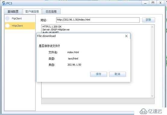
3)202.96.2.1主机使用http协议访问dmz发布到untrust区域服务器的IP地址202.96.1.50
内网PC机配置IP地址及网关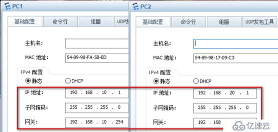
SW1配置如下:
[S1]vlan batch 10 30 40 #批量创建vlan 10 30和40
[S1]int vlan 10         #进入vlan 10
[S1-Vlanif10]ip add 192.168.10.254 24   #配置IP地址
[S1-Vlanif10]undo shutdown     #启用vlan 10
[S1-Vlanif10]quit
[S1]int vlan 30     #进入vlan 30
[S1-Vlanif30]ip add 192.168.30.1 24   #配置IP地址
[S1-Vlanif30]undo shutdown  #启用vlan 30
[S1-Vlanif30]quit
   #相关重复注释我就不一一注释
[S1]int vlan 40
[S1-Vlanif40]ip add 192.168.40.1 24
[S1-Vlanif40]undo shutdown
[S1-Vlanif40]quit
[S1]int eth0/0/1     #进入接口
[S1-Ethernet0/0/1]port link-type trunk   #配置为trunk链路
[S1-Ethernet0/0/1]port trunk allow-pass vlan all   #允许承载所有vlan
[S1-Ethernet0/0/1]quit
[S1]int Ethernet0/0/4   #进入接口
[S1-Ethernet0/0/4]port link-type access    #配置为接入链路
[S1-Ethernet0/0/4]port default vlan 40    #vlan 40加入接口
[S1-Ethernet0/0/4]quit
[S1]int Eth-Trunk 1     #创建链路聚合,编号为1
[S1-Eth-Trunk1]quit
[S1]int eth0/0/2     #进入接口
[S1-Ethernet0/0/2]eth-trunk 1   #配置为链路聚合
[S1-Ethernet0/0/2]quit
[S1]int eth0/0/3     #进入接口
[S1-Ethernet0/0/3]eth-trunk 1   #配置为链路聚合
[S1-Ethernet0/0/3]quit
[S1]int Eth-Trunk 1   #进入接口
[S1-Eth-Trunk1]port link-type trunk   #配置为trunk链路
[S1-Eth-Trunk1]port trunk allow-pass vlan all     #允许承载所有vlan
[S1-Eth-Trunk1]quit
[S1]rip 1     #配置rip
[S1-rip-1]version 2   #版本2
[S1-rip-1]network 192.168.10.0   #宣告直连网络
[S1-rip-1]network 192.168.30.0    #宣告直连网络
[S1-rip-1]network 192.168.40.0   #宣告直连网络
[S1-rip-1]quit
[S1]bgp 300   #配置bgp AS编号300
[S1-bgp]peer 192.168.40.2 as-number 200   #与AS 200的40.2建立邻居
[S1-bgp]peer 192.168.30.2 as-number 300   #与AS 300的30.2建立邻居
[S1-bgp]peer 192.168.30.2 next-hop-local      #配置30.2下一跳可达
[S1-bgp]quit
SW2配置如下:(相关注释请参考SW1)
[S2]vlan batch 20 30 50
[S2]int vlan 20
[S2-Vlanif20]ip add 192.168.20.254 24
[S2-Vlanif20]undo shutdown
[S2-Vlanif20]quit
[S2]int vlan 30
[S2-Vlanif30]ip add 192.168.30.2 24
[S2-Vlanif30]undo shutdown
[S2-Vlanif30]quit
[S2]int vlan 50
[S2-Vlanif50]ip add 192.168.50.1 24
[S2-Vlanif50]undo shutdown
[S2-Vlanif50]quit
[S2]int eth0/0/1
[S2-Ethernet0/0/1]port link-type trunk
[S2-Ethernet0/0/1]port trunk allow-pass vlan all
[S2-Ethernet0/0/1]quit
[S2]int eth0/0/4
[S2-Ethernet0/0/4]port link-type access
[S2-Ethernet0/0/4]port default vlan 50
[S2-Ethernet0/0/4]quit
[S2]int Eth-Trunk 1
[S2-Eth-Trunk1]quit
[S2]int eth0/0/2
[S2-Ethernet0/0/2]eth-trunk 1
[S2-Ethernet0/0/2]quit
[S2]int eth0/0/3
[S2-Ethernet0/0/3]eth-trunk 1
[S2-Ethernet0/0/3]quit
[S2]int Eth-Trunk 1
[S2-Eth-Trunk1]port link-type trunk
[S2-Eth-Trunk1]port trunk allow-pass vlan all
[S2-Eth-Trunk1]quit
[S2]rip 1
[S2rip-1]version 2
[S2-rip-1]network 192.168.20.0
[S2-rip-1]network 192.168.30.0
[S2-rip-1]network 192.168.50.0
[S2-rip-1]quit
[S2]bgp 300
[S2-bgp]peer 192.168.50.2 as-number 200
[S2-bgp]peer 192.168.30.1 as-number 300
[S2-bgp]peer 192.168.30.1 next-hop-local
[S2-bgp]network 192.168.10.0
[S2-bgp]network 192.168.20.0
[S2-bgp]quit
SW3配置如下:
[S3]int eth0/0/3
[S3-Ethernet0/0/3]port link-type trunk
[S3-Ethernet0/0/3]port trunk allow-pass vlan all
[S3-Ethernet0/0/3]quit
[S3]int eth0/0/4
[S3-Ethernet0/0/4]port link-type trunk
[S3-Ethernet0/0/4]port trunk allow-pass vlan all
[S3-Ethernet0/0/4]quit
[S3]vlan batch 10 20 30
[S3]int eth0/0/1
[S3-Ethernet0/0/1]port link-type access
[S3-Ethernet0/0/1]port default vlan 10
[S3-Ethernet0/0/1]quit
[S3]int eth0/0/2
[S3-Ethernet0/0/2]port link-type access
[S3-Ethernet0/0/2]port default vlan 20
[S3-Ethernet0/0/2]quit
R1配置如下:
[R1]int g0/0/0
[R1-GigabitEthernet0/0/0]ip add 192.168.40.2 24
[R1-GigabitEthernet0/0/0]int g0/0/1
[R1-GigabitEthernet0/0/1]ip add 192.168.50.2 24
[R1-GigabitEthernet0/0/1]int g0/0/2
[R1-GigabitEthernet0/0/2]ip add 192.168.60.1 24
[R1-GigabitEthernet0/0/2]int loo0
[R1-LoopBack0]ip add 1.1.1.1 32
[R1-LoopBack0]quit
[R1]ospf 1 router-id 1.1.1.1    #配置ospf进程1,router-id为1.1.1.1
[R1-ospf-1]area 0   #骨干区域,area 0
[R1-ospf-1-area-0.0.0.0]network 192.168.60.0 0.0.0.255  #宣告直连
[R1-ospf-1-area-0.0.0.0]quit
[R1-ospf-1]quit
[R1]bgp 200
[R1-bgp]router-id 1.1.1.1
[R1-bgp]peer 192.168.40.1 as-number 300
[R1-bgp]peer 192.168.50.1 as-number 300
[R1-bgp]peer 192.168.60.2 as-number 200
[R1-bgp]peer 192.168.60.2 next-hop-local
[R1-bgp]quit
R2配置如下:
[R2]int g0/0/0
[R2-GigabitEthernet0/0/0]ip add 192.168.60.2 24
[R2-GigabitEthernet0/0/0]int g0/0/1
[R2-GigabitEthernet0/0/1]ip add 192.168.70.1 24
[R2-GigabitEthernet0/0/1]int loo0
[R2-LoopBack0]ip add 2.2.2.2 32
[R2-LoopBack0]quit
[R2]ospf 1 router-id 2.2.2.2
[R2-ospf-1]area 0
[R2-ospf-1-area-0.0.0.0]network 192.168.60.0 0.0.0.255
[R2-ospf-1-area-0.0.0.0]quit
[R2-ospf-1]quit
[R2]bgp 200
[R2-bgp]router-id 2.2.2.2
[R2-bgp]peer 192.168.60.1 as-number 200
[R2-bgp]peer 192.168.70.2 as-number 100
[R2-bgp]peer 192.168.60.1 next-hop-local
[R2-bgp]quit
R3配置如下:
[R3]int g0/0/0
[R3-GigabitEthernet0/0/0]ip add 192.168.70.2 24
[R3-GigabitEthernet0/0/0]int g0/0/1
[R3-GigabitEthernet0/0/1]ip add 192.168.80.1 24
[R3-GigabitEthernet0/0/1]int loo0
[R3-LoopBack0]ip add 3.3.3.3 32
[R3-LoopBack0]quit
[R3]bgp 100
[R3-bgp]router-id 3.3.3.3
[R3-bgp]peer 192.168.70.1 as-number 200
[R3-bgp]peer 192.168.80.2 as-number 100
[R3-bgp]peer 192.168.80.2 next-hop-local
[R3-bgp]peer 192.168.90.2 as-number 100
[R3-bgp]peer 192.168.90.2 next-hop-local
[R3-bgp]quit
[R3]rip 1
[R3-rip-1]version 2
[R3-rip-1]network 192.168.80.0
[R3-rip-1]quit
R4配置如下:
[R4]int g0/0/0
[R4-GigabitEthernet0/0/0]ip add 192.168.80.2 24
[R4-GigabitEthernet0/0/0]int g0/0/1
[R4-GigabitEthernet0/0/1]ip add 192.168.90.1 24
[R4-GigabitEthernet0/0/1]int loo0
[R4-LoopBack0]ip add 4.4.4.4 32
[R4-LoopBack0]quit
[R4]bgp 100
[R4-bgp]router-id 4.4.4.4
[R4-bgp]peer 192.168.80.1 as-number 100
[R4-bgp]peer 192.168.90.2 as-number 100
[R4-bgp]quit
[R4]rip 1
[R4-rip-1]version 2
[R4-rip-1]network 192.168.80.0
[R4-rip-1]network 192.168.90.0
[R4-rip-1]quit
FW1配置如下:
[FW1]int g0/0/0
[FW1-GigabitEthernet0/0/0]ip add 192.168.90.2 24
[FW1-GigabitEthernet0/0/0]int g1/0/0
[FW1-GigabitEthernet1/0/0]ip add 172.16.1.254 24
[FW1-GigabitEthernet1/0/0]int g1/0/1
[FW1-GigabitEthernet1/0/1]ip add 202.96.1.10 24
[FW1-GigabitEthernet1/0/1]quit
[FW1]bgp 100
[FW1-bgp]router-id 100.100.100.100
[FW1-bgp]peer 192.168.90.1 as-number 100
[FW1-bgp]peer 192.168.80.1 as-number 100
[FW1-bgp]peer 192.168.80.1 next-hop-local
[FW1-bgp]network 0.0.0.0
[FW1-bgp]quit
[FW1]rip 1
[FW1-rip-1]version 2
[FW1-rip-1]network 192.168.90.0
[FW1-rip-1]network 172.16.0.0
[FW1-rip-1]quit
[FW1]security-policy      #配置安全策略
[FW1-policy-security]rule name local     #安全策略名字为local
[FW1-policy-security-rule-local]source-zone local    #定义源区域为local
[FW1-policy-security-rule-local]destination-zone trust   #定义目标区域trust
[FW1-policy-security-rule-local]destination-zone dmz   #定义目标区域dmz
[FW1-policy-security-rule-local]action permit     #允许流量通过
[FW1]security-policy   #配置安全策略
[FW1-policy-security]rule name trust_untrust     #安全策略名字为trust_untrust
[FW1-policy-security-rule-trust_untrust]source-zone trust  #定义源区域为trust
[FW1-policy-security-rule-trust_untrust]destination-zone untrust   #定义目标区域untrust
[FW1-policy-security-rule-trust_untrust]action permit   #允许流量通过
[FW1]security-policy   #配置安全策略
[FW1-policy-security]rule name trust_dmz    #安全策略名字为trust_dmz
[FW1-policy-security-rule-trust_dmz]source-zone trust    #定义源区域为trust
[FW1-policy-security-rule-trust_dmz]destination-zone dmz    #定义目标区域dmz
[FW1-policy-security-rule-trust_dmz]action permit    #允许流量通过
[FW1]security-policy     #配置安全策略
[FW1-policy-security]rule name untrust_to_dmz   #安全策略名字为untrust_dmz
[FW1-policy-security-rule-untrust_to_dmz]source-zone untrust   #定义源区域为untrust
[FW1-policy-security-rule-untrust_to_dmz]destination-zone dmz   #定义目标区域dmz
[FW1-policy-security-rule-untrust_to_dmz]service http   #开启http协议
[FW1-policy-security-rule-untrust_to_dmz]action permit    #允许流量通过
[FW1-policy-security-rule-untrust_to_dmz]quit
[FW1-policy-security]quit
[FW1]nat-policy    #配置NAT策略
[FW1-policy-nat]rule name natpolicy    #NAPT策略名字为natpolicy
[FW1-policy-nat-rule-natpolicy]source-zone trust   #定义转换源区域
[FW1-policy-nat-rule-natpolicy]destination-zone untrust    #定义转换目标区域
[FW1-policy-nat-rule-natpolicy]action nat easy-ip   #定义的转换源和easy-ip建立映射关系
[FW1-policy-nat-rule-natpolicy]quit
[FW1-policy-nat]quit
R5配置如下:
[R5]int g0/0/0
[R5-GigabitEthernet0/0/0]ip add 202.96.1.11 24
[R5-GigabitEthernet0/0/0]int g0/0/1
[R5-GigabitEthernet0/0/1]ip add 202.96.2.254 24
[R5-GigabitEthernet0/0/1]int g0/0/2
[R5-GigabitEthernet0/0/2]ip add 202.96.3.254 24
[R5-GigabitEthernet0/0/2]quit
外部服务器及PC配置IP地址: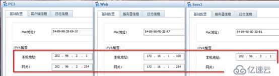
至此已经全部配置完成,满足了实验三个需求,接下来开始验证
1)Pc1和pc2可以ping通dmz区域的172.168.1.100服务器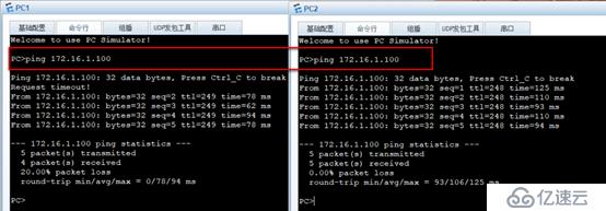
2)Pc1和pc2可以ping通202.96.3.1需要使用easy-IP NAT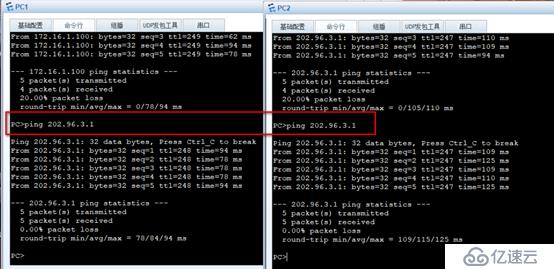
3)202.96.2.1主机使用http协议访问DMZ发布到untrust服务器的IP地址202.96.1.50
WEB服务器创建网页测试文件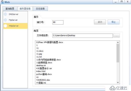
———————本文至此结束,感谢阅读 ——————
免责声明:本站发布的内容(图片、视频和文字)以原创、转载和分享为主,文章观点不代表本网站立场,如果涉及侵权请联系站长邮箱:is@yisu.com进行举报,并提供相关证据,一经查实,将立刻删除涉嫌侵权内容。